


Technical Specifications:
---------------------------------------------------------------------------
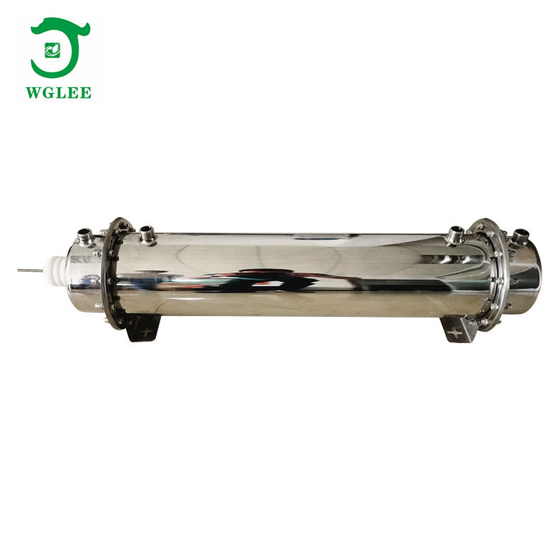
Name: 100G/H Ozone Generator Accessories (High-Voltage Control Power Supply + Cellular Discharge Chamber)
Model: FW-100G
Operating Voltage: AC220V/50H
Power: 25~1000W Adjustable
Gas Supply: Dry and Clean Oxygen or Air; Dew Point ≤0℃, Pressure < 0.15MPa
Cooling Water: Flow Rate >5L/min, Outlet Temperature<35℃, Pressure <0.3MPa
Ozone Output: 100g/H
Gas Flow Rate: Air Source Oxygen Source
Ozone Concentration: Oxygen Source 80-160mg/L; Air Source 15-20mg/L
Operating Ambient Temperature: -10~40℃
Operating Ambient Humidity: Relative Humidity ≤85%
Dimensions: Ozone Discharge Tube:750*170*180mm; Power Supply:220*125*65mm
(Maintain >15cm clearance between power supply edges and metal plates)
Product Structure Description:
------------------------------------------------------------------------
1. The 100g/H ozone generator kit consists of an ozone discharge chamber and a high-voltage drive power supply.
2. Discharge Chamber Features: Internally combines 7 discharge tubes in a honeycomb-like structure. Both electrodes use 316L stainless steel; housing is 304 stainless steel. Dielectric material: high-purity silica quartz tubes with PTFE and fluororubber seals. External electrode water-cooled. Design lifespan >50,000 hours.

Honeycomb Tube Diagram: 100G discharge chamber contains 7 discharge tubes.
3. High-Voltage Power Supply Features: Military-grade variable frequency PCB circuit and vacuum epoxy high-voltage transformer. Key features: IGBT driven, automatic/manual frequency width, soft-start (limits inrush current), over-voltage protection, power converter overheat protection, output short-circuit/open-circuit protection, audible/visual alarms, anti-interference circuit, moisture/corrosion resistant design. Compatible with PLC (0-5V or 4-20mA) control and custom voltage settings. Normal service life >12,000 hours.
4. Power Supply Components:
(1) Potentiometer: Adjusts output power to control ozone concentration/yield (clockwise increases).
(2) High-voltage & Ground Wires: Red silicone HV wire connects to discharge terminal; ground wire connects to tube housing.
5. Power supply uses push-pull topology with soft-start (no inrush current). Power adjustment via potentiometer doesn't alter frequency.
Equipment Application Description
------------------------------------------------------------------------
FW-100G accessories are core components for ozone system assembly. Multiple units can be installed (e.g., 2 sets = 200g/H system). Accepts oxygen/air sources for sterilization/purification, primarily in water treatment. Acclaimed for superior craftsmanship, electrical stability, and extended lifespan.
Installation Instructions
Step 1: Mount power supply on insulating board (fiberglass, ≥5mm thick) in chassis. Maintain >15cm clearance from metal chassis (prevents eddy currents). Ensure convective cooling. Connect HV wire to discharge terminal and ground wire to housing. Keep HV wires >2cm from other components.
Step 2: Cooling Water: Horizontal mounting: any port for inlet/outlet. Vertical mounting: HV terminal upward, inlet bottom, outlet top. Water temperature ≤ ambient, flow >5L/min. Check for leaks. Recirculated or external cooling acceptable.
Step 3: Gas Connections: Port near HV terminal is inlet (standard materials: silicone/PVC). Outlet requires ozone-resistant materials (PTFE/fluororubber/stainless steel). Supply gas must be clean, dry, ≤35℃, dew point<0℃.
Step 4: Mount potentiometer on chassis control panel for user adjustment.
Step 5: Wiring: Keep HV connections short (factory length ~50cm). Prevent contact with other wires. Keep digital/signal wires away from HV components.
Circuit Board Wiring & Debugging
Note: Factory-tested and calibrated. Users typically don't need readjustment. Technicians: Adjust gradually with power on using power analyzer (not ammeter). Do not exceed 1000W. Set external potentiometer to maximum during adjustment.
Usage Precautions
---------------------------------------------------------------------------
1. Inspect for damage/missing parts before installation.
2. Handle components carefully; avoid drops/impacts.
3. Verify gas/water/electrical connections before power-on.
4. Prevent HV leakage to chassis. HIGH VOLTAGE HAZARD.
5. Prohibited in flammable/explosive environments.
6. Maintain cooling water outlet temperature ≤40°C.
7. Avoid prolonged exposure to ozone outlet.
8. Only qualified personnel may open chassis.
9. Prevent water backflow into gas lines during water treatment.
Equipment Routine Maintenance
--------------------------------------------------------------------------
1. Operate in dry, ventilated, clean environment (-10~40°C,<85% RH).
2. Perform maintenance with power disconnected.
3. Suitable for 24/7 continuous operation with adequate cooling.
4. Wring out cleaning cloths thoroughly; prevent water ingress.