


Technical Specifications:
----------------------------------------------------------------------------------------
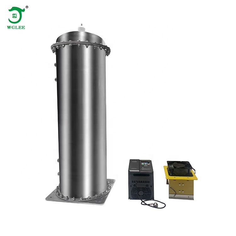
Name: Cellular Type 500G/H Ozone Generator Accessories (Ozone Inverter + High-Voltage Transformer + Cellular Discharge Chamber)
Model: FW-500G
Operating Voltage: AC220V/50HZ
Power: 30~4000W Adjustable
Gas Supply: Dry and Clean Oxygen or Air; Dew Point ≤ -20℃, Operating Pressure < 0.9MPa
Cooling Water: Outlet Temperature < 35℃, Pressure < 0.2MPa.
Port Size: Gas inlet/outlet and water inlet/outlet ports are all 6-point external thread fittings.
Ozone Output: Using Oxygen, flow rate 90~100L/min, Ozone Output ≥ 500g/H
Using Cold Dry Air, flow rate 350~400L/min, Ozone Output ≥ 300g/H
Operating Ambient Temperature: -10~40℃; Optimal Operating Ambient Temperature: -10~25℃
Operating Ambient Humidity: ≤85% RH (No condensation on smooth surfaces)

Special Note: The cellular ozone generator itself is a capacitive load. The capacitance changes with different gas source pressures, causing the power level to vary accordingly. Therefore, under different gas source conditions, the frequency of the power supply must be adjusted to correspond to the stable pressure on-site to control the power output. This prevents insufficient ozone concentration and yield due to inadequate power, or power supply burnout caused by exceeding the rated power value.
Wiring Diagram------------------------------------------------------------------------
Note: Terminal commands are preset at the factory. Connect as shown in the diagram above during assembly.
F13:02 Frequency Adjustment (0-8KHZ)
F01:01 Voltage Adjustment
[Frequency/Voltage adjustment can change the operating power/current. Set at the factory based on no-load conditions. If different site conditions cause changes in operating power/current requiring adjustment, contact the manufacturer.]
(The high-voltage transformer is mounted on an insulating board with edges at least 20 cm away from any metal plate. Ensure adequate heat dissipation inside the chassis.)
Installation Instructions
Step 1: Mount the ozone power supply and high-voltage transformer onto an insulating board (non-conductive material, thickness ≥5mm). Secure the insulating board inside the equipment chassis. Important: Maintain a distance greater than 20 cm between the high-voltage transformer and the metal chassis shell (proximity may cause high-voltage eddy currents affecting performance or causing damage). The high-voltage transformer requires convective air cooling (fan cooling). Mount the discharge chamber inside the chassis; it can be electrically connected to the chassis shell. Connect the high-voltage wire to the discharge chamber's terminal and the high-voltage ground wire to the discharge chamber's shell. Ensure the high-voltage wire is at least 3 cm away from other wires or the chassis; contact is prohibited.
Step 2: Cooling Water Installation: If the discharge chamber is mounted parallel to the base plane, either end can be used for inlet/outlet. If the ozone tube is mounted perpendicular to the plane, the high-voltage wire terminal must face upwards, the water inlet must be at the bottom, and the outlet at the top. After connecting the water pipes, ensure no leaks. Cooling water can be recirculated or supplied externally; installation convenience is key.
Step 3: Gas Inlet and Ozone Outlet Installation: The gas port closest to the high-voltage terminal is the inlet. Use standard materials (e.g., silicone, PVC) for the inlet tubing. The outlet must use ozone-resistant materials (PTFE tube, fluororubber tube, stainless steel pipe, etc.). Ensure gas-tight connections. The gas supplied to the discharge chamber, whether oxygen or air, must be clean, dry, temperature ≤35°C, and dew point below 0°C.
Step 4: Potentiometer Installation: Mount the potentiometer on the chassis control panel for user adjustment. Its primary function is to adjust the ozone power supply's output power, thereby changing the ozone output concentration and yield. Rotate clockwise to increase, counterclockwise to decrease.
Step 5: Wiring Check: After connecting the high-voltage wire and ground wire to the ozone tube, keep the high-voltage wire connection as short as possible (factory length approx. 50 cm). Avoid contact between the high-voltage wire and other lines or objects inside the chassis. Ideally, suspend it independently and sleeve it with silicone or PVC tubing. Other lines, especially digital display wires and online signal detection wires, must not be near high-voltage components (high-voltage transformer, high-voltage wire, ozone tube) to prevent interference.
Usage Precautions
---------------------------------------------------------------------------
1. First, inspect the equipment for damage or missing parts before installation and use.
2. Handle components carefully during installation to avoid dropping or impact damage.
3. After installation, thoroughly check gas lines, water lines, and electrical circuits before powering on.
4. Ensure installation prevents high-voltage leakage to the chassis shell. High Voltage Hazard.
5. Prohibited for use in flammable or explosive environments.
6. Ensure cooling water outlet temperature does not exceed 35°C.
7. Ozone concentration at the outlet is high. Avoid prolonged human exposure to ozone.
8. Do not open the chassis of installed equipment unless you are qualified personnel. General electricians should consult professional maintenance personnel first.
9. When used for water treatment, ensure the gas-water mixing device prevents water backflow into the ozone tube's gas lines to avoid high-voltage short circuits.
Equipment Routine Maintenance
--------------------------------------------------------------------------
1. Installed equipment should be placed in a dry, ventilated, and clean environment. Ambient temperature: -10~40℃; Relative humidity:<85%.
2. Maintenance must be performed with the power cable disconnected.
3. The equipment can operate continuously 24 hours a day, but ensure effective heat dissipation.
4. When cleaning the chassis with a damp cloth, wring it out thoroughly. Do not allow water to splash inside the machine.
After-Sales Service
---------------------------------------------------------------------------
1. One-year warranty from the date of purchase.
2. Quality issues during the warranty period are repaired free of charge. Damage due to installation errors or human factors will incur charges.
Cellular Type 1000G / H Ozone Generator Kit
Technical Parameters:
----------------------------------------------------------------------------------------
Name: 1000G / H Ozone Generator Accessories (High-Voltage Control Power Supply + Air-Cooled High-Voltage Transformer + Cellular Discharge Chamber)
Model: FW-1000G
Operating Voltage: AC 380V / 50HZ
Power: 50 to 8 kW Adjustable
Gas Supply Source: Dry and Clean Oxygen or Air; Dew Point ≤ -20℃, Operating Pressure<0.98MPa.
Cooling Water: Flow Rate 2-3 t/h, Outlet Temperature<35℃, Pressure <0.3MPa.
Port Size: Gas inlet, outlet and water inlet, outlet ports are all 1-inch external thread fittings.
Gas Flow Rate: Air Source 800-900 L/min; Oxygen Source 180-200 L/min
Ozone Concentration: Oxygen Source: 80-140 mg/L; Air Source: 10-20 mg/L
Operating Ambient Temperature: -10~40℃; Optimal Operating Ambient Temperature: -10~25℃
Operating Ambient Humidity: ≤85% RH (No condensation on smooth surfaces)
Special Description: The honeycomb ozone generator itself is a capacitive load. Capacitance varies with gas source pressure, causing power consumption to change accordingly. Therefore, under different gas source conditions, the power supply frequency must be adjusted to match the stable pressure on-site to control power output. This prevents insufficient ozone concentration and yield due to inadequate power, or power supply burnout caused by exceeding the rated power value.
Wiring Schematic Diagram------------------------------------------------------------------------

Note: The terminal command has been set from the factory. Connect according to the figure above during assembly.
F13:02 Frequency Adjustment (0-8KHZ)
F01:01 Voltage Adjustment
[Frequency / Voltage adjustment can change the operating power / current level. Set at the factory based on no-load conditions. If site conditions cause changes requiring adjustment, contact the manufacturer.]
(The high-voltage transformer is installed on an insulating board with edges at least 30 cm away from any metal plate. Ensure adequate heat dissipation inside the box. Maintain >5cm clearance for high-voltage wires.)
Installation Instructions
Step 1: Mount the Ozone power supply and High Voltage Transformer onto an insulating plate (non-conductive material, thickness ≥5mm). Secure the insulating plate inside the chassis. Important: Maintain a distance >30 cm between the High Voltage Transformer and the metal chassis enclosure (proximity may cause high-voltage eddy currents). The High Voltage Transformer requires convective air cooling (fan cooling). Mount the Discharge Chamber inside the chassis; it can be electrically connected to the chassis enclosure. Connect the high-voltage wire to the Discharge Chamber terminal and the high-voltage ground wire to its shell. Maintain >5cm clearance between the high-voltage wire and other lines/chassis; contact is prohibited.
Step 2: Cooling Water Installation: If the Discharge Chamber is installed parallel to the plane, water inlet/outlet can be at either end. If the ozone tube is installed perpendicularly, the high-voltage wire terminal must face upwards, the water inlet must be at the bottom, and the outlet at the top. Ensure no leaks after connection. Cooling water can be recirculated or supplied externally.
Step 3: Gas Inlet and Ozone Outlet Installation: The port near the high-voltage terminal is the inlet. Use standard materials (e.g., silicone, PVC) for inlet tubing. The outlet must use ozone-resistant materials (PTFE tube, fluororubber tube, stainless steel pipe, etc.). Ensure gas-tight connections. Supplied gas (Oxygen or Air) must be clean, dry, temperature ≤35°C, dew point<0°C.
Step 4: Potentiometer Installation: Mount the potentiometer on the chassis control panel for user adjustment. Its primary function is to adjust the ozone power supply output power, changing ozone concentration and yield. Rotate clockwise to increase, counterclockwise to decrease.
Step 5: Wiring Check: Connect the high-voltage and ground wires to the ozone tube using the shortest possible path (factory length ~50cm). Avoid contact with other lines/objects. Ideally, suspend wires independently and sleeve them with silicone or PVC tubing. Keep other lines (especially digital display/signal detection wires) away from high-voltage components (Transformer, Wire, Ozone Tube) to prevent interference.
Usage Precautions
---------------------------------------------------------------------------
1. Inspect equipment for damage/missing parts before installation/use.
2. Handle components carefully during installation; avoid drops/impacts.
3. Before powering on, thoroughly check gas lines, water lines, and electrical circuits.
4. Ensure installation prevents high-voltage leakage to the chassis. High Voltage Hazard.
5. Prohibited in flammable/explosive environments.
6. Ensure cooling water outlet temperature ≤35°C.
7. High ozone concentration at outlet; avoid prolonged human exposure.
8. Do not open the chassis unless qualified. General electricians must consult professionals first.
9. For water treatment, prevent water backflow into the ozone tube gas lines to avoid short circuits.
Equipment Daily Maintenance
--------------------------------------------------------------------------
1. Operate equipment in a dry, ventilated, clean environment (-10~40°C,<85% RH).
2. Perform maintenance only with the power disconnected.
3. Equipment can run 24/7 continuously; ensure adequate heat dissipation.
4. Wring out cleaning cloths thoroughly; prevent water ingress into the machine.