


Technical Parameters
-----------------------------------------------------------------------------
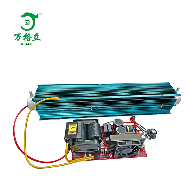
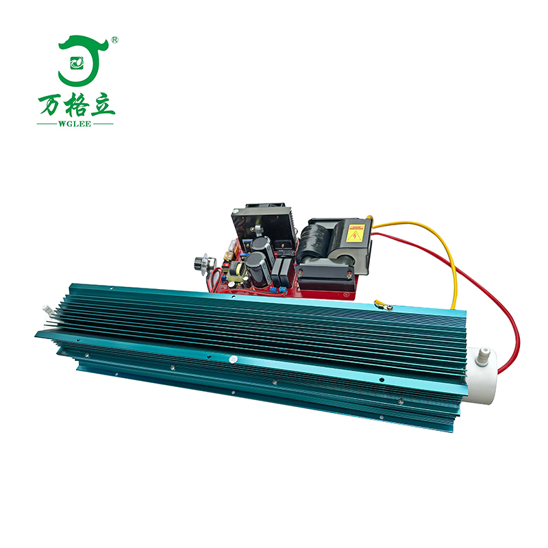
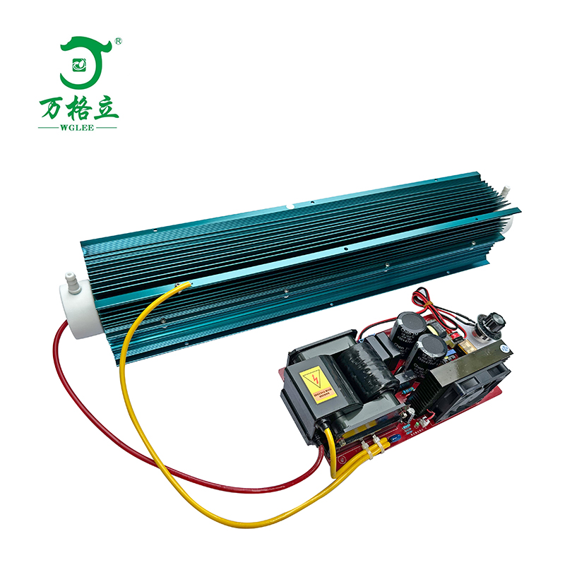
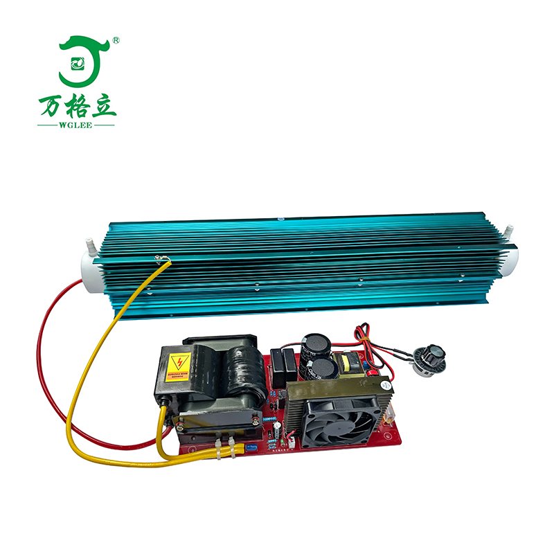
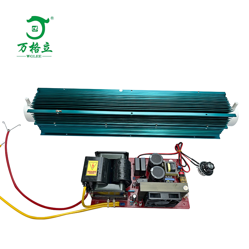
Name: 50G/H Ozone Generator Accessories (Module Power Supply + Ozone Tube)
Model: KS-50G
Operating Voltage: AC220V/50HZ
Power Supply Power: 10-450W Adjustable
Cooling Method: Air-cooled
Gas Supply Source: Dry, clean oxygen or air
Ozone Output: 50G/H
Ozone Concentration: Oxygen source 70-120mg/L; Air source 8-12mg/L
Inlet Flow Rate: Oxygen source 10L/min Air source 75-80L/min
Discharge Gap: 0.5mm
Operating Ambient Temperature: -7~45℃
Operating Ambient Humidity: ≤85%RH
Dimensions: Ozone Tube (L*W*H): 610*102*102mm Power Supply: 250*135*85mm
Net Weight: 6.9KG
Gas Nozzle Size: φ10*6mm Hose Barb Fitting
Mounting Dimensions: Power Supply Mounting Hole Spacing: 115*210mm, Hole Diameter: φ4.5mm.
Ozone Tube Mounting Hole Spacing: 91*391mm, Hole Diameter: φ4.2mm
Product Structure Description:
-------------------------------------------------------------------------------
1. The 50G/H Ozone Generator Accessories include: Ozone Tube and Adjustable High-Voltage Power Supply.
2. Composition and Features of the Ozone Tube: Internal electrode made of 316L stainless steel, external electrode made of aluminum alloy heat sink. Dielectric material is quartz tube composed of over 99.7% silicon dioxide, combined with PTFE and fluororubber sealing components. External electrode is air-cooled. The main features of the quartz tube generator are high dielectric constant, good dielectric toughness (less prone to damage during transportation), low thermal expansion coefficient, and pressure resistance of 0.3MPa. Normal service life is generally over 20,000 hours.
3. Composition and Features of the High-Voltage Power Supply: Vacuum epoxy high-voltage transformer; FR4 circuit board PCB; Short circuit, open circuit, overcurrent protection; Power adjustable; Normal service life over 18,000 hours.
Equipment Application Description
-------------------------------------------------------------------------------
The KS-50G Ozone Generator Accessories are the main core components of an ozone machine. The supplied gas source can be either oxygen or air. They can be used in places requiring ozone sterilization or purification, generally applied in space sterilization and disinfection, deodorization, decolorization, and various raw water/wastewater treatment.
Equipment Installation and Usage Instructions
-------------------------------------------------------------------------------
Step 1: Mount the high-voltage power supply and ozone tube onto an insulating board. Fix the insulating board inside the equipment chassis. Important: Maintain a distance of more than 5 cm between the ozone tube/high-voltage power supply and the metal chassis shell (if the high-voltage part is too close to the metal shell, it may cause high-voltage eddy currents, affecting performance or causing damage). Install the ozone tube within the space for convective airflow in the chassis, ensuring the fan on the machine can blow onto the heat sink of the ozone tube during operation, guaranteeing stable air-cooling for the external electrode.
Step 2: Installation of inlet and ozone outlet: The gas nozzles on the ozone tube are not designated inlet/outlet; either end can be used. The inlet pipe can be made of silicone or PVC tubing. Use ozone-resistant tubing (e.g., PTFE, fluororubber) for the outlet connection. Ensure there are no gas leaks. The gas entering the ozone tube inlet, whether oxygen or air, must be clean, dry, with a temperature not exceeding 45°C and humidity not exceeding 70%RH.
Step 3: Wiring Check: After connecting the high-voltage wire and high-voltage ground wire to the ozone tube, try to connect the high-voltage wire using the shortest possible path. The high-voltage wire supplied with the accessory is approximately 30CM long. During installation, you may shorten it as needed based on position. Avoid the high-voltage wire touching other wires or objects inside the chassis. If possible, use an 8MM inner diameter silicone tube to sleeve the high-voltage wire for enhanced insulation. Insert the high-voltage wire with the welded spring into the middle of the ozone tube. Keep all other wiring away from the high-voltage components (transformer, high-voltage wire, ozone tube), as the high voltage may interfere with their normal function.
Schematic Diagram of Ozone Tube Structure:

Wiring Method between High-Voltage Power Supply and Ozone Discharge Tube:

The area between the two dotted lines represents the hollow interior of the ozone tube's internal stainless-steel electrode. Insert the high-voltage wire with the welded retaining spring into this space. Use a screwdriver to push the spring clip approximately into the middle of the ozone tube. Connect the other high-voltage wire to the aluminum alloy heat sink (external electrode) of the ozone discharge tube.
(Note: Do not let the two high-voltage wires cross each other)
Usage Precautions
-------------------------------------------------------------------------------
1. Upon receiving the goods, first check the equipment for any damage or missing parts. Only proceed with installation and use after confirming no issues.
2. During component installation, handle with care to avoid dropping and damaging parts.
3. After completing equipment installation, double-check the gas lines and electrical circuits before powering on.
4. Ensure the installation prevents any high-voltage leakage to the chassis shell. High voltage is dangerous.
5. Do not use in flammable or explosive environments.
6. Ensure good convective air cooling. The operating temperature of the ozone tube must not exceed 60°C.
7. The ozone concentration at the outlet is high. Avoid prolonged human contact with ozone. Wait at least 20 minutes after the machine stops before entering a space where ozone has been released.
8. Non-professionals should not open the equipment chassis. General electricians should only open the chassis after consulting professional maintenance personnel.
9. When the equipment is used for water treatment, ensure the gas-water mixing device prevents water backflow into the ozone tube's gas line, as this can cause a high-voltage short circuit.
Routine Maintenance
-------------------------------------------------------------------------------
1. The equipment should be placed in a dry, ventilated, and clean environment. Ambient temperature should be between -7~40℃, relative humidity less than 85%RH.
2. Maintenance must be performed with the power disconnected.
3. Regularly inspect the ventilation grilles on the equipment. Clean promptly if excessive dust accumulates and reinstall them properly.
4. The equipment can operate continuously for 24 hours, but ensure good ventilation and heat dissipation.
5. When cleaning with a damp cloth, wring it thoroughly. Avoid splashing water droplets into the machine interior.